


Digital Display Meter 0-10V 0-20mA 4-20mA 2-10V Analog Input with RS485/Relay Output

$67.50 – $76.20 Inc. GST
- Description
- Additional information
- Reviews (0)
Description
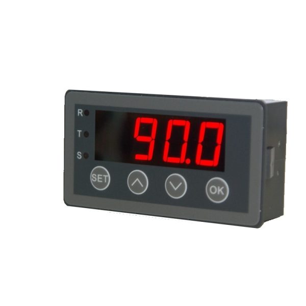
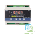
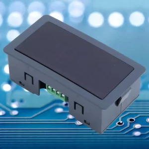
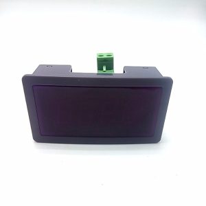
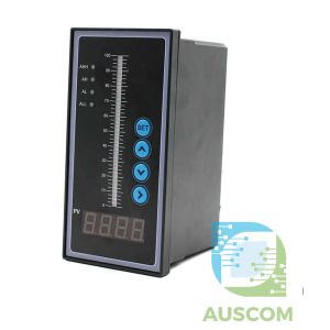
Introducing the Versatile Digital Display Meter for Analog Inputs: 0-10V, 0-20mA, 2-10V, 4-20mA
Upgrade your data monitoring with our multifunctional Digital Display Meter, designed to handle a variety of analog output sensors. Whether you’re tracking temperature, pressure, liquid levels, or motor speeds, this meter adapts to multiple applications with ease.
Key Features:
- Universal Analog Input Compatibility: Designed to work seamlessly with various sensors that feature analog outputs. Common applications include temperature transmitters, pressure gauges, frequency converters, motor speed sensors, and liquid level indicators.
- Flexible Input Options: The meter supports both current (4-20mA, 0-20mA) and voltage (0-10V, 2-10V) inputs, giving you the flexibility to connect to a wide range of sensors.
- Pre-configured Default Ranges: The meter comes pre-configured for 0-10V, 2-10V, 0-20mA, and 4-20mA inputs. If needed, customize bias and gain settings for other input ranges within these parameters.
- Customizable Display: The default display mode is percentage-based, but you can easily adjust it to suit your specific needs through settings such as F0-2 to F0-4.
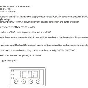
- Advanced Connectivity Options: The RS485 interface-equipped variant enables easy networking, allowing multiple meters to communicate and display data across multiple units using the Modbus-RTU protocol.
- Compact and Easy to Install: With dimensions of 79 x 43 x 25mm and an installation opening of 76.5 x 39.5mm, the meter can be effortlessly integrated into existing setups.
Model Variants:
Choose the version that best suits your needs:
- Standard Edition: Perfect for general applications requiring basic functionality.
- RS485 Version: For networked setups, allowing data sharing and multi-display installations using Modbus-RTU.
- Relay Output Version: Includes a 3A 30VDC/3A 250VAC relay output, ideal for setups requiring control capabilities alongside monitoring.
Easy Parameter Configuration:
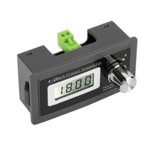
Adjust settings like input type, filter times, gains, and offsets using the simple button interface. The 0.56-inch 4-digit digital tube display ensures clear parameter visualization for easy adjustments.
Seamless Networking (RS485 Version):
For RS485-equipped models, multiple meters can be connected and communicate with one another via Modbus-RTU. This feature simplifies data sharing and multi-display setups, providing a unified view of your system.
Relay Control (Relay Output Version):
The relay output variant allows you to define precise control conditions. Set comparison values, hysteresis intervals, and control types to ensure your system performs as expected.
Effortless Communication Setup:
Tailor communication parameters, including address assignment, baud rate, data format, and response delays, to perfectly fit your network and data-sharing needs.
User-Friendly Interface:
Easily navigate through settings with the intuitive interface. Adjust input types, display ranges, and more to match your specific application requirements.
Elevate your data visualization with our Digital Display Meter. Whether you’re tracking temperature, pressure, or any other analog measurement, this flexible tool adapts to your needs. With options for standard, RS485, or relay output models, you’ll find the perfect solution for streamlined monitoring, enhanced control, and simplified communication.
Navigation and Setup:
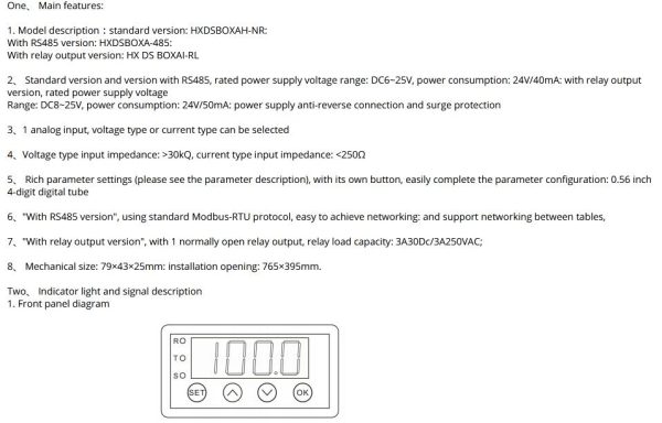
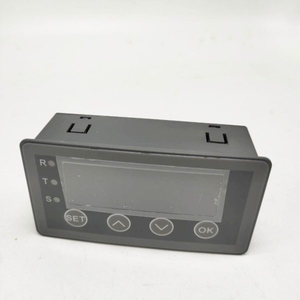
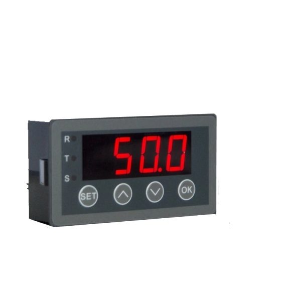
Two、 Indicator light and signal description
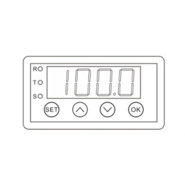
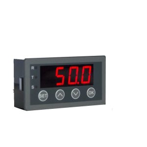
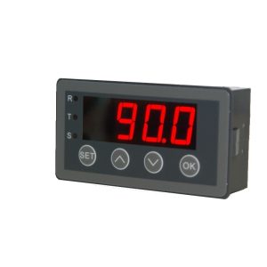
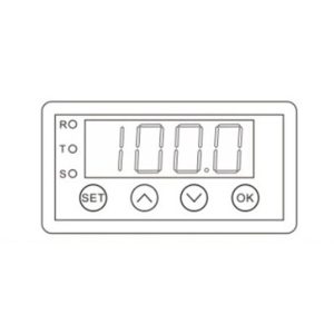
1. Front panel diagram

2. Indicator light:
a. Only “with RS485 version” is useful: R communication receives data indication: T communication sends data indication
b. Only the “with relay output version” has: S indicator light on when the relay is closed
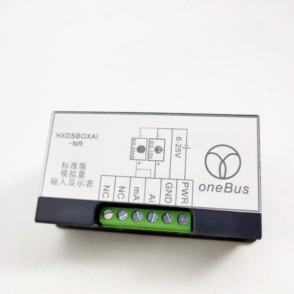
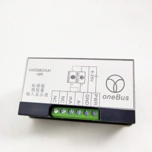
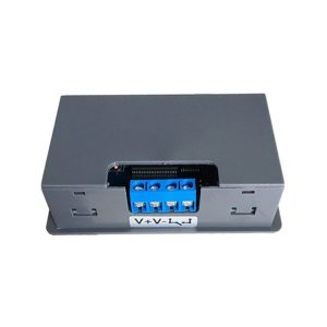
3.Port signal description
| signal | Explanation | |
| PWR | Connect to the positive pole of the power supply (standard version and version with RS485: DC6~30V: with relay output version: DC8~30V) | |
| GND | Power and signal ground | |
| Ai | Power and signal ground | |
| mA | Current-type analog input signal configuration interface, short-circuited with A, then configured as current-type input | |
| With RS485 version | 485- | RS485 signal is negative |
| 485+ | RS485 signal is positive | |
| With relay output version | KA | Relay normally open contact output port |
| KB | ||
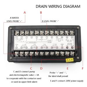
4.Common wiring diagram:

5. Button and digital tube display state transition diagram:

Special note: In the third-level menu, click OK to save the modified parameter value and return to the previous menu, the parameter number is automatically increased by one; and click the SET button to directly return to the previous menu without saving the modified parameter value . Long press or
or to make the adjustment value change quickly
Three、Parameter description
The parameters are described as follows
1. F0 Attendant array display
| Parameter | parameter name | Scope and description | Defaults | Read write |
| FO-0 | Collected value monitoring | Monitor the percentage of the current analog input value. Range: 0-100.0% | read-only | |
| FO-1 | Display value monitoring | In the display value in “Monitoring Menu” is calculated by F00, F0-2~F04. | read-only | |
| FO-2 | Display accuracy | The number of decimal places displayed in the “Monitor Menu”, range: 0-3. | 1 | Read write |
| FO-3 | Show minimum | In the “monitoring menu”, the value corresponding to “acquisition value” is 0%, the range: -1999~9999 | 0 | Read write |
| FO-4 | Show maximum | In the “Monitoring Menu”, the value corresponding to the “Acquisition Value” is 100.0%, the range: 19999~9999 | 1000 | Read write |
2. F1 parameter group-analog configuration parameters
| Parameter | parameter name | Scope and description | Defaults | Read write |
| F1-0 | Input type selection | 0:0~10V or 0~20mA corresponds to 0~100.0% | 0 | Read write |
| F1-1 | Input filter time | 1: 2~10V or 4-20mA corresponds to 0~100.0%, and it is 0 when it is lower than 2V or 4mA. | 0.200 | Read write |
| F1-2 | Input gain | Analog input filter time, range: 0-10.000S. The greater the filtering time, the stronger the filtering.
Range: 0~1000.0%. |
100.0 | Read write |
| F1-3 | Input offset | -99.9~99.9%, with 10V or 20mA as 100.0%. | 0.0 | Read write |
| F1-4 | Keep | Unused | 0 | Read write |
| F1-5 | Enter the parameter setting selection | 0: Long press SET button for 3s to enter the parameter setting mode: 1: Keep pressing SET button for more than 3s, and
Press OK to enter parameter setting mode |
0 | Read write |
The formula of analog input gain and bias is: adjustment result = (acquisition value + offset) × gain
F2 parameter group relay output dosing (with relay Output version)
| Parameter | parameter name | Scope and description | Defaults | Read write |
| F2-O | Relay output status configuration | When the output conditions are met, the relay output status:
0: No control (always open) 1: Relay closed 2: Relay open (not satisfied Closed on condition) |
0 | Read write |
| F2-1 | Condition type | 0: greater than comparison value 1, 1: less than comparison value 2.
2: Greater than comparison value 1 and less than comparison value 2. |
0 | Read write |
| F2-2 | Comparison value 1 | Range: 0-100.0% | 50.0 | Read write |
| F2-3 | Comparison value 2 | Range: 0-100.0%. | 50.0 | Read write |
| F2-4 | Hysteresis interval | In order to prevent the relay output from operating frequently near the comparison value, hysteresis interval parameters are introduced
Range: 0.0%~80.0%. |
Read write |
Examples are given to illustrate the action mechanism of the hysteresis interval: for example, if “F2 condition type” is selected as “0: greater than comparison value 1”, “F22 comparison value 1” is set as 50.0%, and “F24 hysteresis interval” uses the default value of 5.0%. When power on, the collected value increases gradually. When it is greater than 50.0% + 5.0% / 2, the output condition is satisfied. If the collected value decreases, it needs to be less than 50.0% – 5.0% / 2 to reach the non output condition.
F7 communication parameters and software version (communication parameters are “with RS485 version” for use)
| Parameter | parameter name | Scope and description | Defaults | Read write |
| F7-0 | Local address | Range: 1~247 | 1 | Read write |
| F7-1 | Baud rate | 0:1200bp;1: 2400bp5;2:480bps: 3: 9600bps
4:1920bps;5: 38400bps |
3 | Read write |
| F7-2 | Data Format | 0:8,1, None (8 data bits, 1 stop bit, no parity)
1:8,1, Even (8 data bits, 1 stop bit, even parity) 2:8,1,Odd (8 data bits, 1 stop bit, odd parity 3:8,2, None (8 data bits, 2 stop bits, no parity) |
0 | Read write |
| F7-3 | Response delay | Communication response delay time 0~500ms | 5 | Read write |
| F7-4 | Communication type | Use above V1.02
0: The display table is a Modu slave, and the user host can read the collected values of the display table: 1: The display table is a network slave between the tables, and can receive the display data of the display table set as the master: 2: The display table is the network host between the tables, and the display value is sent to the slave display table through the broadcast address 3: The display table is the inter-table networking host, and the display value is sent to the slave by means of address polling Display table, address polling range is: 1~F70 value. |
0 | Read write |
| F7-5 | Parameter recovery | Set to 111 to restore the parameters to the factory settings: other values are invalid. | 1313 | read-only |
| F7-6 | Model code | Module model code 0521H | 0.1 | |
| F7-7 | Send interval time | The interval time for the host to send the data table during master-slave communication. Range: 0.1~100. 0s | Read write | |
| F7-8 | Software version number | Set module software version number, two decimal places. 1.00 corresponds to the software version number is v1.00 | read-only |
Four、Communication protocol and communication method of “with R485 communication version”
1. The user host accesses the collected value of the display table
Communication uses standard Modbus-RTU protocol, read with multiple read command 03H. The returned parameter value is the integer displayed by the nixie tube with the decimal point removed. For example, the F0-0 nixie tube display value is 60.0, and the value read by communication is 600. The Modbus register address has a corresponding relationship with the parameter, such as
The Modbus register address corresponding to F72 is 0702H, that is, 7 in F7-2 is the high 8-bit value, and 2 in F72 is the low 8-bit value.
For example, read the parameters F0-0 and F0-1 parameter values (the F1 parameter group uses the default parameter settings), the format is as follows:
| host sends a selective dance | Slave (HXDSB0XAI) response data | |||
| Slave address is F70 | 01H | Slave address ( F7-0) | 01H | |
| Mbus function number | 03H | Modbus function number | 03H | |
| Start address (high byte) | 00H | Returns the number of bytes (4 bytes) | 04H | |
| Start address (low byte) | 00H | High byte of address content | 02H | |
| Read word count (high byte) | 00H | low byte of the content of 000 address | 58H | |
| Read word count (low byte) | 02G | High byte of 0001H address content | 02H | |
| CRC (low byte) | C4H | Low byte of 0001H address content | 58H | |
| CRC (high byte) | OBH | CRC (low byte) | 7AH | |
| CRC (high byte) | C2H |
In the above example, the read f0-0 and f0-1 are both 0258h = 600, that is, the collected value f0-0 is 60.0%; the displayed value f0-0 is 60.0
2. Network Description:
Through the inter table networking, the display value of the data collected from the master table can be transmitted to the slave table through RS485. There can be only one master table in a network, and there can be multiple slave tables. In use, only the main table needs to set the corresponding display range, and the slave table does not need to set the display range.


Additional information
| Weight | 200 g |
|---|---|
| Dimensions | 260 × 160 × 40 mm |
| Type | Standard, Relay, RS485 |
Only logged in customers who have purchased this product may leave a review.


Reviews
There are no reviews yet.